
Product D
Product D is a custom hardware controller for the Product C software, designed for performance and ease of use.
Video Demos and download links at the bottom of this page.

As my culminating project for Music Technology, I aimed to demonstrate the skills I acquired during my studies. Integrating my proficiency in electronics, coding, and design, I embarked on creating a hardware controller for the Product C software—a tool I envisioned utilizing for my personal composition and experimentation.
Design Problem
Using the laptop trackpad for live performance becomes cumbersome and tedious when using only software controls for Product C.
How can I seamlessly integrate the creative process and minimize any disruptive elements?

Opted for a microcontroller due to cost and time constraints, avoiding the development of a proprietary logic controller.
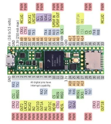
Identified scarcity of microcontrollers capable of reliably handling a complex Max patch. Chose Teensy 4.1 for its compatibility with audio-related projects.
Research and Ideation
During the initial phase, I brainstormed a list of "dream features" and sketched a rudimentary diagram resembling the software to enhance usability. Next, I assessed the cost-benefit ratios for each feature, exploring alternatives for those outside the project scope due to time or cost constraints.
Key Findings
Addressed pin shortage and enhanced design appeal incorporating I2C components Adafruit NeoTrellis and OLED display..
Leveraged the computer connection, eliminating the need for an additional audio input and external power source.
Planning
While the core of this project revolves around a hardware interface, it necessitates the expansion of the software as well, in order to receive MIDI control messages. This dual-track development strategy requires dedicated attention to ensure proper functionality between the digital and physical components.

Proof of Concept
With the initial design now streamlined into a workable schematic, my next step involved crafting a proof of concept on a breadboard. This phase allowed for thorough testing of both the software and hardware synthesis, focusing on key components such as buttons, rotary encoders, and potentiometers. Once this proof of concept was successfully validated, I could proceed to the final design phase of the project.

The software design for the proof of concept was categorized into three key areas: potentiometers, buttons, and the rotary encoder. Each component would interact with Max in a unique way, contributing to the overall functionality of the hardware controller.
Potentiometers
Potentiometers are controlled using MIDI CC, a protocol tailored for knob-like parameter adjustments. In Max, each knob is recognized as a distinct controller, triggering specific responses based on its movement.
Software Development
Buttons
Buttons present a straightforward implementation, emitting a MIDI note-on signal to activate their respective functions. In Max, the program monitors for the designated MIDI note, prompting the execution of the associated function when the button is toggled.
Rotary Encoders
Rotary encoders follow an implementation more akin to buttons. Utilizing the encoder's native library, the system monitors the dial's movement in terms of "clicks." With each click, a MIDI note-on signal is sent. In Max, logic will increment or decrement the associated value depending on direction of movement.
Iterative Refinement
Two significant modifications arose from the initial proof of concept. Firstly, the integration of a second Teensy microcontroller was necessary. Secondly, there was a consolidation of channel controls for the sequencer.
Teensy
The extensive number of controls surpassed the available physical pins on the Teensy. To address this limitation, a second Teensy microcontroller was introduced, communicating with the first via UART. A straightforward communication protocol was established, signaling the start of a data stream with a designated byte, followed by specifying the expected byte count. Within this protocol, one of the bytes indicated potentiometer updates, ensuring real-time adjustments as the controls were manipulated.
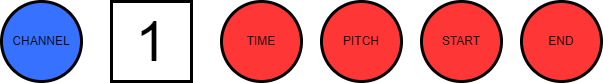
Channel Controls
To optimize physical space and reduce parts costs, I consolidated the controls of each sequencer channel. Instead of duplicating controls for every channel, I implemented a single set of controls with a channel select knob. Rotary encoders were chosen for shared controls, allowing adjustments through incremental clicks. This design choice allowed the storing of the data in Max, and the click simply registering a decrement or increment of a set value.
Preliminary Hardware Development
After revising the initial proof of concept, a reassessment of the interface led to strategic changes. The planned use of Adafruit NeoTrellis keypads for sequencer buttons evolved to include the looper buttons, enhancing performance usability with constant access to all four channels. Simultaneously, the consolidation of the ADSR envelope and effects controls into a single array, controlled by a channel and effect select knob, resulted in a streamlined hardware design, optimizing both space and size.


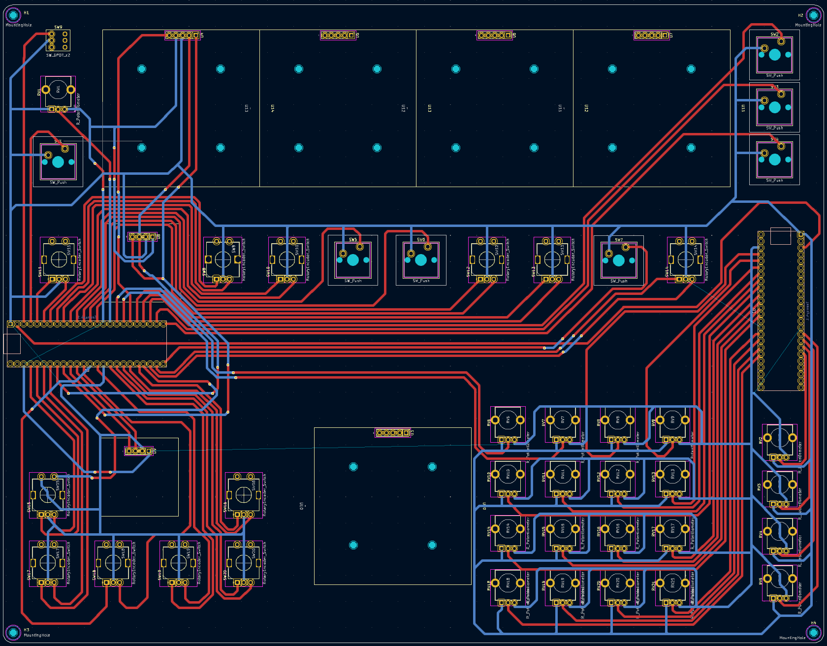
PCB Design
In the PCB design phase, I optimized trace implementation by repositioning Teensy 2 to the right, away from other controls. The effects array exchanged places with the looper array, and the channel select controls were moved to the left of the sequencer channel controls for enhanced clarity and functional alignment.
Enclosure Design
In crafting the enclosure, I opted for a straightforward design from Makercase featuring finger joints for easy assembly. The case, laser-cut from black matte acrylic to minimize fingerprints, showcases control labels etched directly onto the surface for a clean and functional aesthetic.
Hardware-Software Integration

In the subsequent phase, the expansion of hardware controls brought forth challenges in their integration with the existing software structure. Thorough testing and troubleshooting were essential to address these issues effectively. The detailed exploration of encountered challenges and their subsequent solutions laid the foundation for the final assembly, ensuring a refined and robust hardware-software synergy.
Roadblocks and Solutions
Roadblock
Serial communication between two Teensy microcontrollers worked as designed. However, the planned expansion to allow Max to communicate the state of the sequencer grid to turn on LEDs introduced significant program lag.
Solution
The resolution involved removing the feature, aligning with the hardware's goal to minimize reliance on software interaction. However, the random step button relied on serial communication to update NeoTrellis grid LEDs. To address this, I internally generated a randomly sized list of numbers within the Teensy, ensuring LED activation without dependence on Max. This allowed cutting the feature without losing program functionality.
Reflection
This project was a great exercise in project scoping. It’s easy to brainstorm ideas for improved function, but there needs to be a balance between expendable resources and what will be able to deliver the most value in the short-term. Additionally, getting the opportunity to work on so many unfamiliar aspects of the design process proved to be incredibly valuable for further identifying an appropriate scope. If I had more time, I would have liked to explore some of the additional feature ideas for improving performance.
Demonstration
You'll find the Arduino code and Max patches available on my GitHub repository. These resources are essential for anyone interested in the hardware-software interaction of this project. Feel free to explore, download, and experiment with these files to gain a deeper understanding of the project's inner workings